
User guide
This guide shows how to go from a drawing or a 3D model to G-code for your machine. It describes Millwise 0.8. The program is in early development, so some details can look a little different in newer versions.
- Installation and first start
- The window
- Files and projects
- Machine, stock and zero
- Selecting and editing curves
- 2D operations
- 3D machining
- Tools
- Simulation
- G-code export
- Keyboard and mouse
- When something goes wrong
1. Installation and first start
Download Millwise-…-x86_64.AppImage from the
latest release. It is one file, there is
nothing to install:
chmod +x Millwise-*-x86_64.AppImage
./Millwise-*-x86_64.AppImage
You can also give a file to open: ./Millwise-*.AppImage part.dxf.
- Graphics. Millwise draws with the graphics card. On NVIDIA cards, and
when the default graphics fail, it switches to OpenGL by itself. You can
choose yourself with
--gl(OpenGL) or--vulkan. - Language. Polish or English, following your system. Change it in View → Język / Language.
- Settings are kept in
~/.config/millwise/: the tool library (tools.json), the machines (machines.json) and the program settings (settings.json). Copy this folder to move your tools and machines to another computer.
On the first start the tool library gets a basic set of cutters and one example machine. Set up your own machine first (see Machine, stock and zero).
2. The window
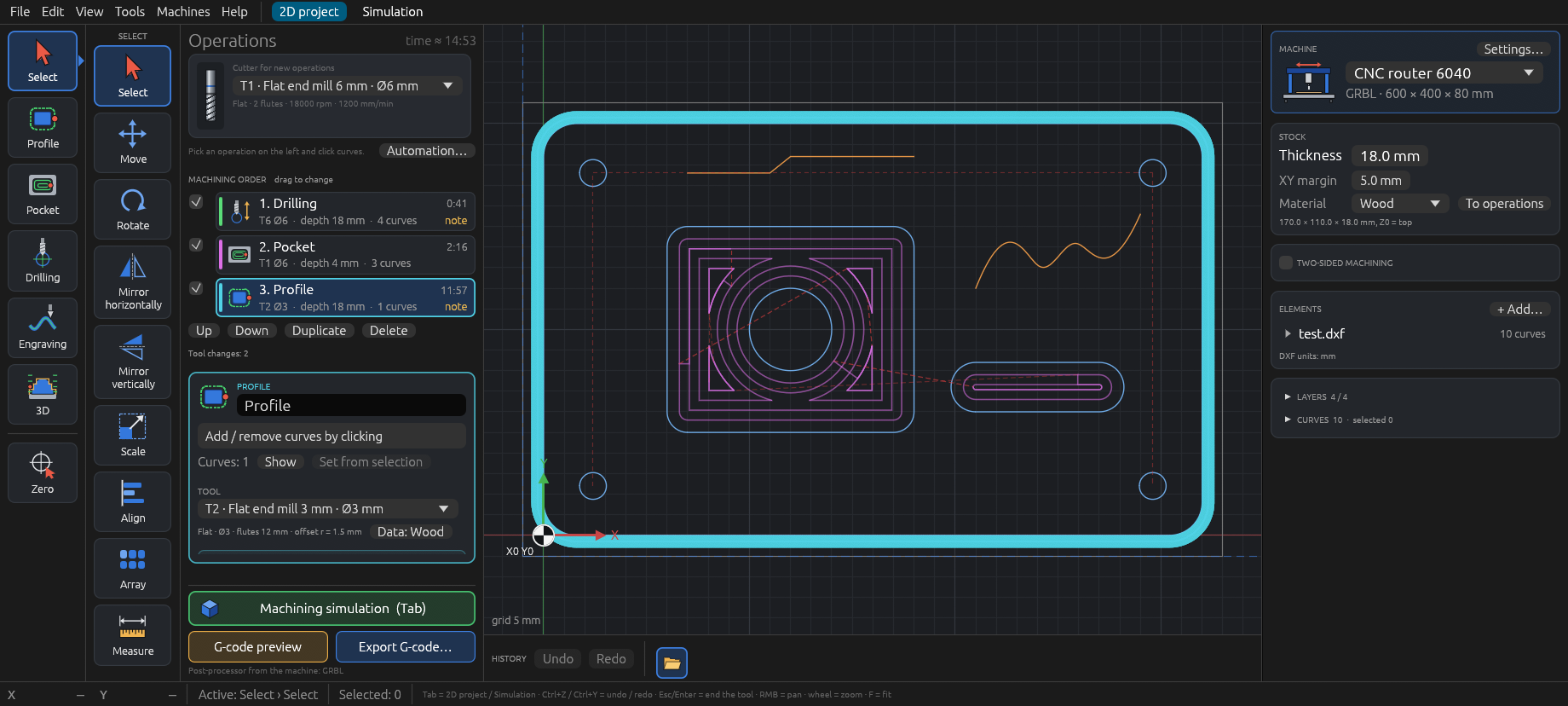
- Tabs at the top: 2D project (the drawing and the operations), 3D model (shown when the project has a 3D model: an STL file, a relief from a photo or a shape from curves) and Simulation. Tab switches between the 2D project and the simulation.
- Toolbar on the far left: big buttons for the groups (Select, Profile, Pocket, Drilling, Engraving, 3D, Zero) and, next to them, the variants of the chosen group.
- Operations next to the toolbar: the list of operations in the order of machining and, below it, the settings of the selected operation.
- Right panel: the machine, the stock, two-sided machining, the elements of the project (files and models), layers and curves.
- History bar (View → History): every change as one step; click a step to go back to it.
- Status bar at the bottom: hints for the current mode, messages and the cursor position.
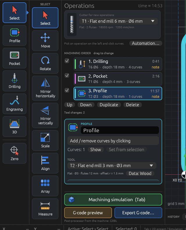
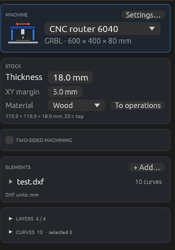
Mouse: the wheel zooms, the right or middle button moves the view, F fits everything on screen. Clicking an empty place in the drawing closes the settings of the operation.
3. Files and projects
| Command | What it does |
|---|---|
| File → Open DXF / project (Ctrl+O) | Opens a DXF drawing, an STL model, a photo (JPG, PNG, BMP — as a relief) or a .millwise project as a new project. |
| File → Add (Ctrl+I) | Adds more files to the current project. You can pick several at once or drop files on the window. New elements are placed next to the old ones and stay selected, so you can move them right away. |
| File → Save (Ctrl+S) / Save as (Ctrl+Shift+S) | Saves everything in one .millwise file: the curves, the models, the operations, the stock, copies of the tools used. |
| File → Export G-code (Ctrl+E) | Writes the program for the machine, see G-code export. |
DXF. Lines, arcs, circles, polylines (with bulges), splines, ellipses and blocks are read. The units come from the file; if the file does not say, millimetres are assumed and the right panel shows the units used. The layers of the drawing are kept: you can hide them and use them in automation.
STL. Binary and text STL files. The model gets its own tab, see 3D machining.
Photos. JPG, PNG and BMP images become a relief, see Relief from a photo. A project has one 3D model: a new STL file or photo replaces the previous one.
4. Machine, stock and zero
Machine
Choose the machine at the top of the right panel; Settings… (or Machines → Machines…) opens the machines window.
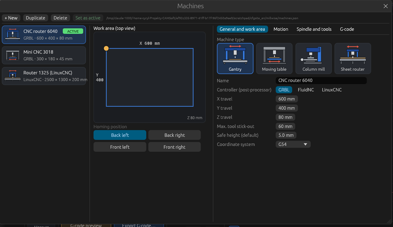
- Machine type: gantry, moving table, column or flatbed (plotter), and the controller: GRBL, FluidNC or LinuxCNC.
- Work area: travel in X, Y and Z, the homing corner, the longest tool stick-out, the safe height and the work coordinate system (G54…).
- Motion: maximum feeds, rapids and acceleration (used for the time estimate and the checks).
- Spindle: minimum and maximum speed and the spin-up time.
- Tool change: a pause (M0), M6, or one G-code file per tool; optionally a tool change position in machine coordinates (G53).
- Equipment: coolant (M7/M8) and a Z probe.
- G-code tab: file extension, decimals, G64, G2/G3 arcs or only lines, N line numbers, comments, your own start and end of the program.
Every operation is checked against the machine. Too deep, too fast or outside the work area shows as a warning in the operation and before export.
Stock
- Thickness of the board. Z0 is the top of the stock.
- XY allowance: the stock is the size of the drawing plus this margin on each side.
- Material (wood, MDF, aluminium, acrylic…). To operations copies the speeds and feeds for this material from the tool library to all operations.
Program zero
The Zero group in the toolbar puts the XY zero in the bottom left corner, the centre or the top left corner of the stock, or at a point you click (it snaps to corners and circle centres). Set the same point on the machine before you run the program.
5. Selecting and editing curves
The Select group has the tools for the drawing:
| Tool | Use |
|---|---|
| Select | Click a curve, drag a frame for many. Shift or Ctrl + click adds to the selection. Selected curves can be dragged with the mouse. |
| Move, Rotate, Scale | Exact values in the panel; the change is shown live and is one step in the history. |
| Mirror horizontally / vertically | Right away, around the centre of the selection. |
| Align | Selected curves to each other: left, right, top, bottom edge or centre. |
| Array | Rows and columns with a gap between the copies; the copies are added to the operations of the original. |
| Measure | Click two points (snaps to corners and circle centres): ΔX, ΔY, distance and angle. |
Edit menu: undo (Ctrl+Z), redo (Ctrl+Y), cut, copy, paste (at the mouse cursor), delete curves (Delete), select all (Ctrl+A), deselect (Esc). The Curves list in the right panel can select all closed curves or all circles (for drilling) at once.
Text (in the Engraving group): type the text, choose a font and the height of capital letters, click where to place it. The letters become curves for engraving, pockets or V-carving.
6. 2D operations
Making an operation
- Choose a group and a variant in the toolbar, e.g. Profile → Outside.
- Click a curve. The operation is created and you can click more curves to add or remove them. Enter or Esc ends the mode.
- Set the operation on the left: tool first, then the depth, the step down and the rest. The Data: (material) button fills the speed and the feeds from the tool for the material of the stock.
- Look at the toolpath in the drawing, then in the simulation.
Operations are machined from the top of the list. Drag them to change the order; Order by tool puts the operations with the same tool together and the cut-outs at the end. The checkbox turns an operation off without deleting it. The panel shows the number of moves and the estimated time.
Types
| Operation | Variants and settings |
|---|---|
| Profile | Outside, inside or on line. Climb or conventional, entry straight, by ramp or by arc lead-in (enters in the waste, leaves no mark), stock to leave, finishing pass (the last pass at full depth takes the rest off, at its own feed), tabs (number, width, height). |
| Corners | Click an inside profile or a pocket: the cutter reaches into each corner (dog-bone), so a square part fits in. |
| Offset, zigzag or adaptive (HSM: small, even step-over and rounded loops, kind to the tool). Curves inside become islands. Wall stock to leave and a finishing pass. | |
| Drilling | Single, peck (retract every set depth) or hole milling (a helix, for holes larger than the tool). |
| Engraving | On the path, on the left or on the right of the line. |
| V-carving | The depth follows the width of the shape; the depth set above is the limit. Needs a V or an engraving cutter. |
Automation
Tools → Automation… does several things in one step (one step in the history, too: Ctrl+Z undoes it all):
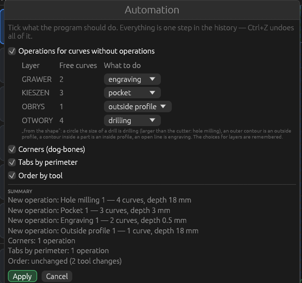
- Operations for free curves, layer by layer. “From the shape” decides by itself: a circle of a drill size is drilled (larger than the tool: hole milling), an outer contour gets an outside profile, a contour inside the part an inside profile, an open line engraving. The choices for each layer are remembered.
- Corners in all inside profiles and pockets.
- Tabs by perimeter on outside profiles: about one tab per 150 mm, from 2 to 12.
- Order by tool, with the cut-outs at the end.
Two-sided machining
Tick Two-sided machining in the right panel and choose the flip axis (along X or Y, through the centre of the stock). Add dowel holes makes two holes on the axis, outside the part, through the board and into the spoilboard, as the first operation of side A. In each operation choose the board side: operations of side B are mirrored and go to their own G-code file. After flipping the board onto the dowels, set Z0 on the new top.
7. 3D machining
The model
Open or add an STL file. The view switches to the 3D model tab: the model in the stock, the toolpaths of the 3D operations and the toolbar with only the operations that work on a model.
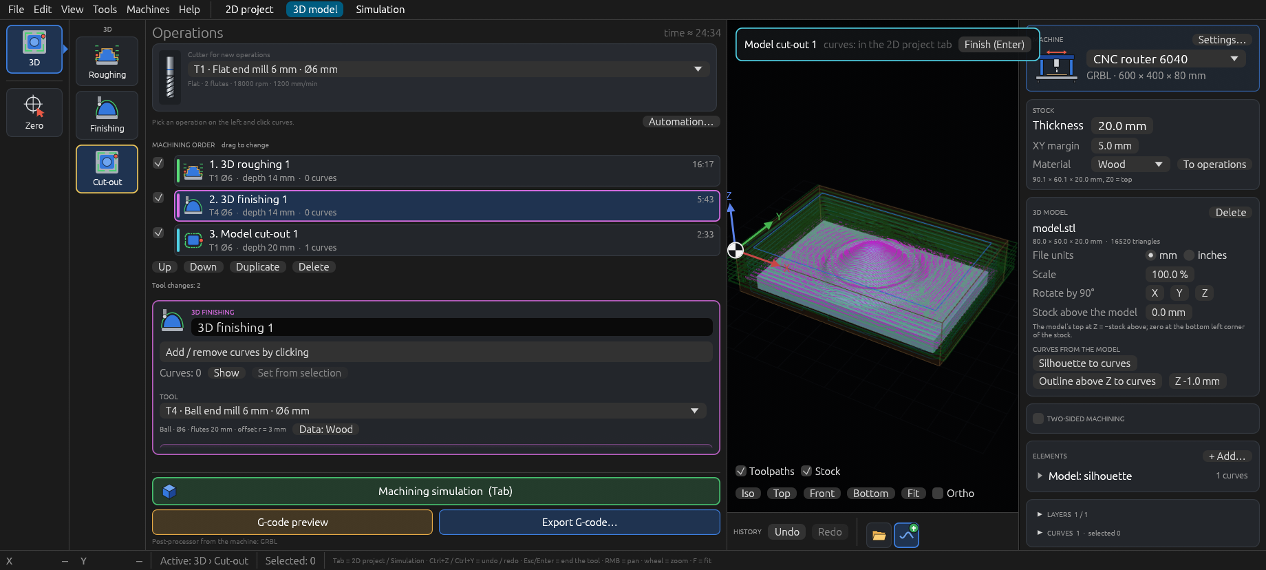
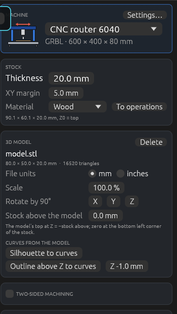
The model card in the right panel:
- File units (mm or inches) and scale.
- Rotate by 90° around X, Y or Z, to put the side you want to machine on top.
- Stock above the model: the top of the model is at Z = −this value, the zero is in the bottom left corner of the stock. The stock thickness follows the model height plus this value.
- Curves from the model: the silhouette (the model seen from above) and the outline above Z (where the model is higher than a given Z) become curves in the 2D project, e.g. for a cut-out profile or a 2.5D pocket around the model.
If the model has undercuts (places hidden under other parts when seen from above), a warning shows how large they are: those places cannot be machined from the top. Turn the model or machine it from two sides.
Relief from a photo
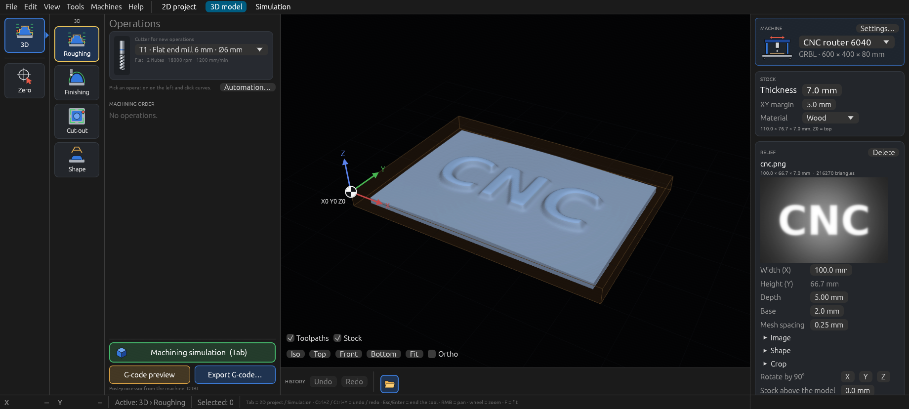
Open or add a JPG, PNG or BMP image instead of an STL file and Millwise turns it into a 3D model: bright places are higher, dark ones lower. The model card then shows the photo and its settings:
- Width (X) — the height (Y) follows the proportions of the photo.
- Depth — the height difference between the darkest and the brightest place.
- Base — material left under the lowest point.
- Smoothing — blurs the photo, removing noise and grain; larger values give softer shapes.
- Mesh spacing — smaller gives more detail but takes longer (at most 1000 points on the longer side).
- Dark is higher — for pictures in which the raised parts are dark.
Under Image, Shape and Crop there are filters, and the picture in the card shows the heights after them (brighter = higher) as you change them:
- Black / white point and Auto levels — use the full depth; gamma raises or lowers the dark places.
- Denoise removes specks and keeps edges, smoothing softens, sharpen brings out fine details.
- Mirror — left and right swapped, e.g. for a stamp.
- Flat background — everything below a threshold lies flat on the base.
- Steps — only a few height levels, like contour lines.
- Oval — only an oval in the middle, e.g. for a portrait; frame — a flat raised border of a given width and height.
- Crop — cut off the edges of the photo.
Changes are applied when you release the mouse or press Enter. The relief is then machined like any model: roughing, finishing with a ball or tapered ball cutter, cut-out. Photos with soft light and a plain background work best; a portrait usually needs some smoothing.
Shape from curves
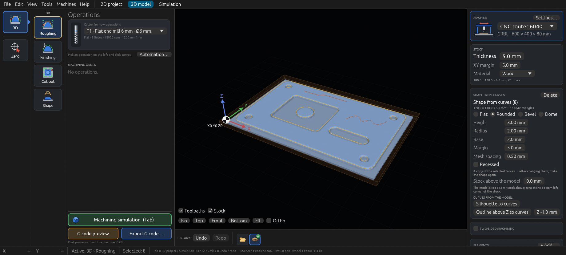
Select closed curves in the 2D project — lettering made with the Text tool, a logo from a DXF, any outline — and click 3D › Shape. They become a 3D model standing exactly on the curves; holes in letters stay holes. In the model card choose the edge profile: flat, rounded (radius), bevel (angle) or dome (highest in the middle of each shape), and the height, base, margin and mesh spacing. Recessed sinks the shape into a flat top instead (a bowl, recessed lettering). The model keeps a copy of the curves: after changing them, make the shape again.
Operations
| Operation | What it does |
|---|---|
| Roughing | Removes most of the material in Z levels around the model, with extra levels just above flat areas. Leaves stock on the model for finishing. Without curves it covers the whole stock; closed curves selected in the 2D project limit it to the inside. |
| Finishing — Parallel | The tool is lowered onto the model in dense points: it touches the surface without cutting into it. Best for gentle slopes and flat areas. Pass spacing shows the expected scallop height; pass angle and second time across (at 90°) make steep sides smoother. Best with a ball or tapered ball cutter, after roughing. |
| Finishing — Waterline | Around the model at constant heights, for steep walls. Flat areas are left for the parallel finishing. |
| Finishing — Combined | Both in one operation: waterlines where the surface is steeper than the split angle (45° by default), parallel passes where it is gentler, with a small overlap so no strip is left between them. |
| Finishing — Spiral / Radial | One continuous spiral from the centre outwards, or passes from the centre like spokes — for domes, bowls and rosettes. The centre is the middle of the model, or of the selected curves (e.g. a circle around a dome). |
| Rest only | Finishing only where a larger tool (chosen in the operation) could not reach: narrow valleys and corners. Rest thicker than skips thin leftovers. |
| Cut-out | An outside profile along the silhouette of the model, with tabs, to cut the part out of the stock. |
Every finishing operation can be limited to a slope range: e.g. 0–2° (Flat only) machines just the horizontal places — handy with a flat cutter on the floor around a relief — and 50–90° only the steep walls.
The depth of a 3D operation is the lowest point the tool goes to (outside the model). 3D toolpaths are computed in the background: the operation shows “computing…” and the window keeps working. G-code can be exported when the computation is done.
8. Tools
Tools → Tool library… opens the library shared by all projects. Tools are grouped by type, the smallest diameter first.
| Type | Use |
|---|---|
| Flat | Profiles, pockets, roughing. |
| Ball | 3D finishing. |
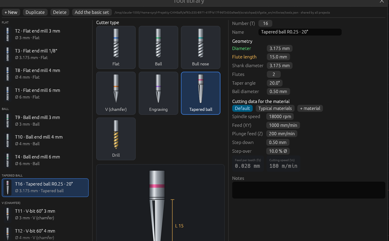
| Tapered ball | A V-shaped body with a hemispherical tip: strong and thin, ideal for fine 3D finishing. Set by the taper angle and the ball diameter. |
| Bull-nose | Flat with rounded corners: roughing and finishing of flat areas. |
| V | Chamfers, engraving, V-carving. |
| Engraving | A cone with a small flat tip: engraving and V-carving. |
| Drill | Drilling. |
Each tool has a number (the T in G-code), the diameter, the shank, the flute length, the number of flutes, and cutting data per material: speed, feed, plunge feed, step down and step-over. The drawing in the window shows the real shape of the tool.
On the first start the library gets a basic set: flat, ball and V cutters and drills in 3, 4 and 6 mm, an engraving cutter and a tapered ball cutter. Projects keep copies of the tools they use; when you open a project with tools that are not in your library, they are added.
Cutter for new operations above the operation list sets the tool that new operations get.
9. Simulation
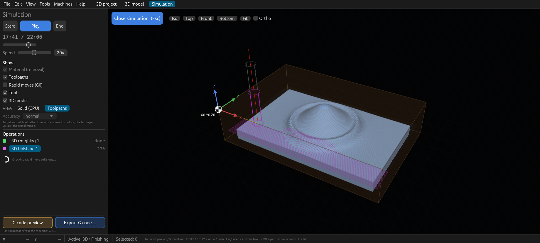
The Simulation tab (Tab) shows the whole program on the stock.
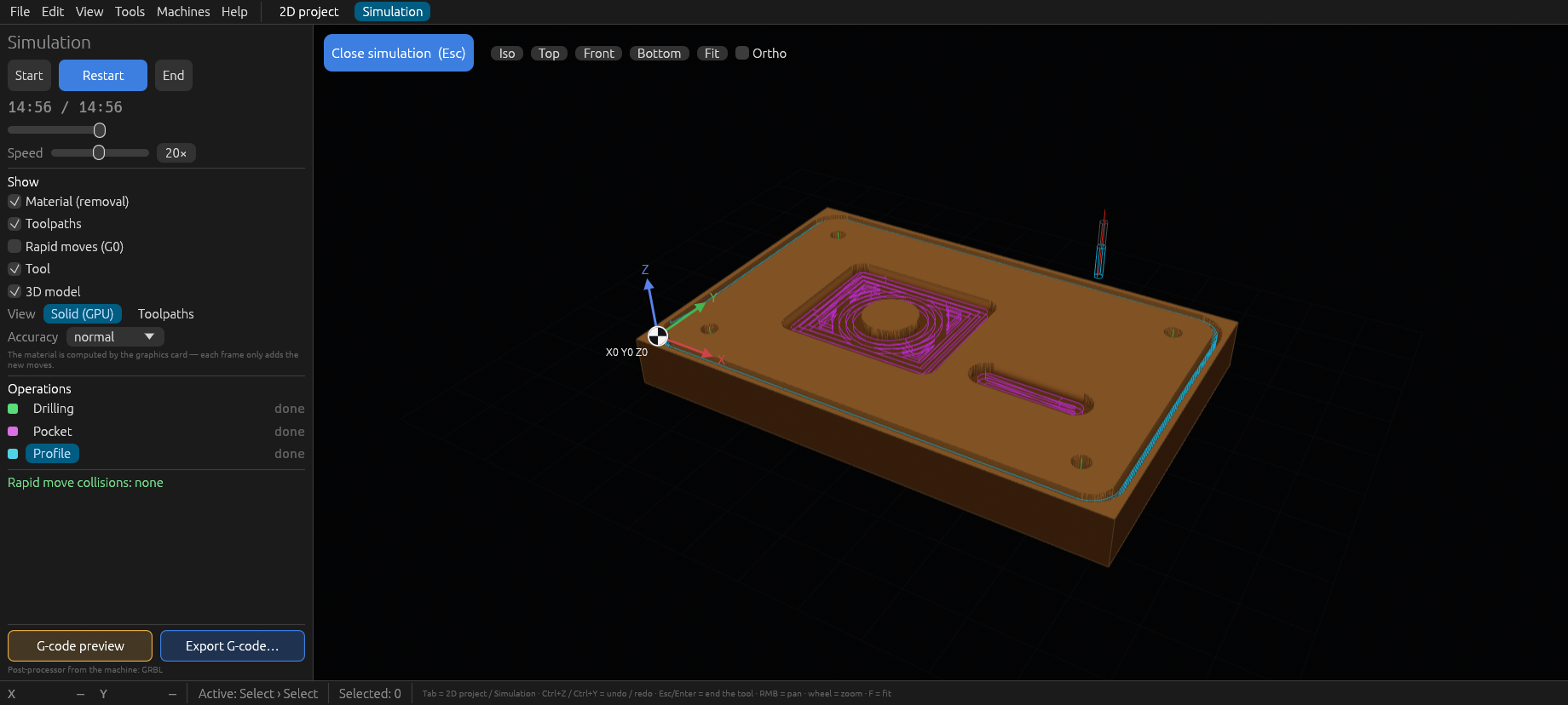
- Play (Space), pause, speed, restart, end, and the slider to seek. Click an operation in the list to jump to its start.
- Show: the material, the 3D model, the toolpaths, the rapid moves (G0) and the tool. The tool position and the depth are shown below.
- Side: for two-sided projects, side A or B (B on the flipped board).
- Rapid moves into the material are checked for the whole program and listed as collisions.
There are two ways to show it:
- Solid (CPU) or Solid (GPU): the material is removed move by move. 2D projects always get the exact solid computed by the processor — clean, vertical walls. For 3D machining and very dense programs, with View → Material simulation on the graphics card (GPU) turned on (the default), the graphics card does it and it stays smooth for programs of any size; without it the processor computes the exact solid, slowly for dense 3D finishing.
- Toolpaths: the target model with the moves already made in the colour of their operation, the layer being cut in yellow and the moves still to come darker. Instant for any size. Finished operations stay visible; only during a 3D operation the earlier 3D ones are hidden (roughing does not cover finishing).
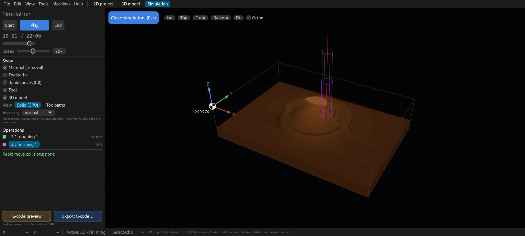
On a weak (for example integrated) graphics card that struggles, turn the GPU option off.
10. G-code export
File → Export G-code… (Ctrl+E) writes the program for the chosen machine. G-code preview in the operation panel shows the code before saving.
- The program uses the post-processor of the machine (GRBL / FluidNC or LinuxCNC) with its own start and end, units, arcs and line numbers.
- Tool change as set for the machine: a pause, M6, or one file per tool.
- Two-sided projects give one file for each side.
- Before saving, Millwise lists the warnings: operations outside the work area, too deep for the tool, without a toolpath or still computing.
Always check the first run in the air or on scrap.
11. Keyboard and mouse
| Key | Action |
|---|---|
| Ctrl+O | Open a DXF, STL, photo or project |
| Ctrl+I | Add files to the project |
| Ctrl+S / Ctrl+Shift+S | Save / save as |
| Ctrl+E | Export G-code |
| Ctrl+Z | Undo |
| Ctrl+Y, Ctrl+Shift+Z | Redo |
| Ctrl+X / C / V | Cut / copy / paste curves |
| Delete | Delete selected curves, or the selected operation |
| Ctrl+A | Select all curves |
| Esc / Enter | End the current mode, deselect |
| Tab | 2D project ↔ simulation |
| F | Fit the view |
| Space | Play / pause the simulation |
| Wheel | Zoom |
| Right or middle button | Move the view (in 3D: the left button turns it) |
| Shift / Ctrl + click | Add to the selection |
The same list is in Help → Keyboard shortcuts.
12. When something goes wrong
- The window does not open or is black: start with
--gl. If it still fails, start it from a terminal and send the messages in an issue. - The simulation is slow: check that View → Material simulation on the graphics card (GPU) is on, or use the Toolpaths view. On a weak card that is slower with the GPU, turn it off.
- A 3D operation takes long: a smaller pass spacing and a bigger model mean more work; the window keeps working while it computes. A slightly larger spacing or curves that limit the area help.
- “No toolpath”: the operation has no curves, the tool is too big for the shape, or the depth is zero.
- Found a bug or have an idea? Open an issue, in English or Polish, with the project file if you can.